- Bayraklı/Izmir TURKEY
- Email: info@zenithar.net
 English
 Français

Core Steel
The purpose of a transformer core is to provide a low-reluctance path for the magnetic flux linking primary and secondary windings.
In doing so, the core experiences iron losses due to hysteresis and eddy currents flowing within it which, in turn, show themselves as heating of the core material. In addition, the alternating fluxes generate noise, which, in the case of a large system transformer, for example, can be as invasive in the environment as a jet aircraft or an internal combustion engine at full throttle.
Core losses, though small in relation to the transformer throughput, are present whenever the transformer is energised. Thus they represent a constant and significant energy drain on any electrical system. It has been estimated that some 5% of all electricity generated is dissipated as iron losses in electrical equipment, and in the UK alone in the year 1987/88 the cost of no-load core losses in transformers was estimated at £110 million. At that time around 109 units of electricity were estimated to be wasted in core losses in distribution transformers each year, equivalent to seven million barrels of oil to produce it and releasing 35 000 tonnes of sulphur dioxide and four million tonnes of carbon dioxide into the atmosphere. The cost implications identified above were, of course, particularly exacerbated by the significant increase in energy costs initiated by the oil crisis of the early 1970s.
Not surprisingly therefore, considerable research and development resource has been applied to electrical steels and to transformer core design in recent years directed mainly towards the reduction of losses but also to the reduction of noise. As a result a great deal of progress has been made and many changes have taken place since the basic principles of modern power transformer design and construction were laid down in the 1920s and 1930s.
Core loss is made up of two components: the first, the hysteresis loss, is proportional to the frequency and dependent on the area of the hysteresis loop, which, in turn, is a characteristic of the material and a function of the peak flux density; the second is the eddy current loss which is dependent on the square of frequency but is also directly proportional to the square of the thickness of the material. Minimising hysteresis loss thus depends on the development of a material having a minimum area of hysteresis loop, while minimising eddy current loss is achieved by building up the core from a stack of thin laminations and increasing resistivity of the material in order to make it less easy for eddy currents to flow.
The components of core loss can be represented by the expressions:
Hysteresis loss, Wh = k1 f Bmaxn watts/kg
and Eddy current loss, We = k2 f2 t2 Beff / ρ watts/kg
where k1 and k2 are constants for the material
f is frequency, Hz
t is thickness of the material, mm
ρ is the resistivity of the material
Bmax is maximum flux density, T
Beff is the flux density corresponding to the R.M.S. value of the applied voltage
n is the ‘Steinmetz exponent’ which is a function of the material. Originally this was taken as 1.6 but with modern materials and higher flux densities n can vary from 1.6 to 2.5 or higher.
In practice the eddy current term is a complex one and can itself be considered to consist of two components: the first truly varies as the square of frequency times material thickness and flux density as indicated by the expression above. This can be calculated in accordance with classical electromagnetic theory and is referred to as the classical eddy current loss; the second is dependent on the structure of the material such as grain size and magnetic domain movement during the magnetising cycle and is known as anomalous loss or residual loss. Anomalous eddy current loss can account for around half the total loss for any particular steel. It is this anomalous loss which can be greatly reduced by special processing of the core material, so that this forms the basis of most of the modern approaches towards the reduction of core loss. More will be said about this later.
The first transformers manufactured in the 1880s had cores made from high grade wrought iron and for a time Swedish iron was preferred. However, in about the year 1900 it was recognised that the addition of small amounts of silicon or aluminium to the iron greatly reduced the magnetic losses. Thus began the technology of specialised electrical steel making.
Hot-rolled Steel
The addition of silicon reduces hysteresis loss, increases permeability and also increases resistivity, thus reducing eddy current losses. The presence of silicon has the disadvantage that the steel becomes brittle and hard so that, for reasons of workability and ease of core manufacture, the quantity must be limited to about 4%. The elimination of impurities, including carbon, also has a significant effect in the reduction of losses so that although the first steels containing silicon had specific loss values of around 7 W/kg at 1.5 T, 50 Hz, similar alloys produced in 1990 having high levels of purity have losses less than 2 W/kg at this condition.
As briefly mentioned above, electrical sheet steels have a crystalline structure so that the magnetic properties of the sheet are derived from the magnetic properties of the individual crystals or grains and many of these are dependent on the direction in the crystal in which they are measured.
The crystals of steel can be represented by a cube lattice as shown in Figure 1 The principal axes of this lattice are designated by x, y, z coordinates enclosed in square brackets, [100], which represents the axis along the cube edge. Planes intersecting the vertices of the cubes are similarly designated by coordinates enclosed in round brackets, (110), representing the plane intersecting diagonally opposite edges.
In the crystal lattice the [100] direction is the easiest direction of magnetisation, the [110] direction is more difficult and the [111] is the most difficult. Silicon steel laminations of thickness around 0.35 mm used in transformers, in the USA until the 1940s and in the UK until somewhat later, were produced by a hot-rolling process in which the grains are packed together in a random way so that magnetic properties observed in a sheet have similar values independent of the direction in which they are measured. These represent an average of the properties for all directions within the individual crystals. The materials are known as isotropic.
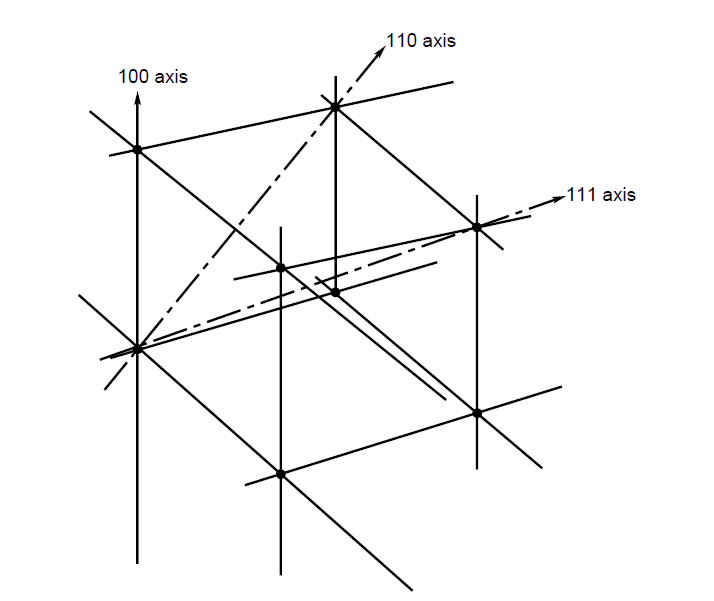
Figure 1 100 direction cube edge is easiest direction of magnetisation; 110 direction cube face diagonal is more difficult; 111 direction long diagonal is the most difficult
Figure 1 100 direction cube edge is easiest direction of magnetisation; 110 direction cube face diagonal is more difficult; 111 direction long diagonal is the most difficult
Grain-oriented Steel
It had been recognised in the early 1920s that the silicon steel crystals were themselves anisotropic, but it was not until 1934 that the American N. P. Goss patented an industrial production process, which was chiefly developed by ARMCO in the USA, that commercial use was made of this property. The first commercial quantities were produced in 1939. The material was the first commercial grain-oriented cold-rolled silicon steel. It had a thickness of 0.32 mm with a loss of 1.5 W/kg at 1.5 T, 50 Hz.
The material is cold reduced by a process set out in Figure 2 This has formed the basis of the production of cold-rolled grain-oriented steels for many years. The initially hot-rolled strip is pickled to remove surface oxides and is then cold rolled to about 0.6 mm thickness from the initial hot band thickness of 2 2.5 mm. The material is given an annealing to recrystallize the cold-worked structure before cold rolling again to the final gauge. Decarburisation down to less than 0.003% carbon is followed by coating with a thin magnesium oxide (MgO) layer. During the next anneal, at 1200°C for 24 hours, purification and secondary recrystallization occur and the magnesium oxide reacts with the steel surface to form a thin magnesium silicate layer called the glass film or Forsterite layer. Finally, the material is given a flattening anneal, when excess magnesium oxide is removed and a thin phosphate coating is applied which reacts with the magnesium silicate to form a strong, highly insulating coating.
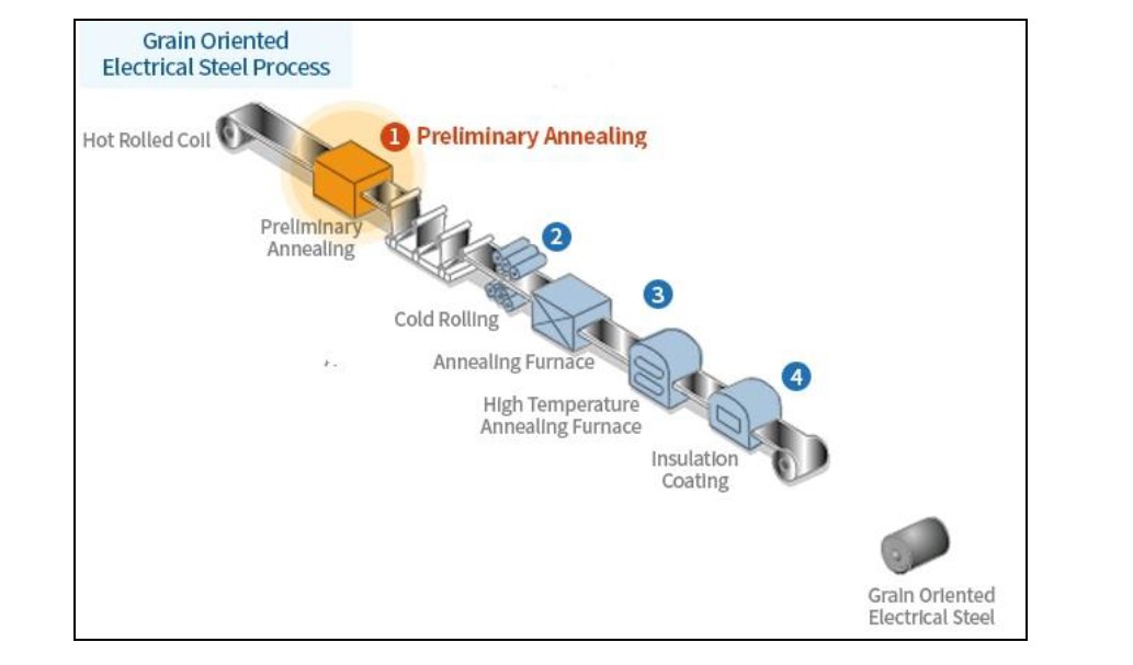
Figure-2
During hot rolling, small particles of manganese sulphide, which has been added to the melt as a grain growth inhibitor, precipitate out as the steel cools. At the same time, some crystals with the Goss texture, that is, having the required orientation, are formed along with many other orientations. After the cold rolling, nuclei with the Goss texture recrystallise during the decarburisation anneal, as the material develops a ‘structure memory’. The grain size, at this stage, is around 0.02 mm diameter, and these increases in the Goss-oriented grains at over 800°C during the high-temperature anneal when the manganese sulphide particles retard the growth of other grains. During this secondary recrystallization process, the Goss grains each consume 106 – 107 primary grains and grow through the thickness of the sheet to diameters of 10 mm or more.
High-permeability steel
Use of cold-rolled grain-oriented steel as described above continued with only steady refinement and improvement in the production process until the late 1960s. However, in 1965 the Japanese Nippon Steel Corporation announced a step-change in the quality of their electrical steel: high-permeability grain oriented silicon steel. The production process is shown in Figure 3 Production is simplified by the elimination of one of the cold rolling stages because of the introduction of around 0.025% of aluminium to the melt and the resulting use of aluminium nitride as a growth inhibitor. The final product has a better orientation than cold-rolled grain-oriented steel (in this context, generally termed ‘conventional’ steel), with most grains aligned within 3° of the ideal, but the grain size, average 1 cm diameter, was very large compared to the 0.3 mm average diameter of conventional material. At flux densities of 1.7 T and higher, its permeability was three times higher than that of the best conventional steel, and the stress sensitivity of loss and magnetostriction were lower because of the improved orientation and the presence of a high tensile stress introduced by the so-called stress coating. The stress coating imparts a tensile stress to the material which helps to reduce eddy-current loss which would otherwise be high in a large-grain material.

Figure-3 Schematic view of production
The total loss is further offset by some reduction in hysteresis loss due to the improved coating. However, the low losses of high-permeability steels are mainly due to a reduction of 30-40% in hysteresis brought about by the improved grain orientation. The Nippon Steel Corporation product became commercially available in 1968, and it was later followed by high-permeability materials based MnSe plus Sb (Kawasaki Steel, 1973) and Boron (Allegheny Ludlum Steel Corporation, 1975).
Domain-refined steel
The continued pressure for the reduction of transformer core loss identified above led to further improvements in the production process so that in the early 1980s the Nippon Steel Corporation introduced laser-etched material with losses some 5 8% lower than high-permeability steel. By 1983 they were producing laser-etched steels down to 0.23 mm thick with losses as low as 0.85 W/kg at 1.7 T, 50 Hz.
It has been briefly mentioned above, in defining the quantity ‘anomalous eddy-current losses, which this arises in part due to magnetic domain wall movement during the cycles of magnetisation. Messrs Pry and Bean [3.1] as early as 1958 had suggested that in a grain-oriented material anomalous eddy current loss is proportional to the domain wall spacing and inversely proportional to sheet thickness. This is illustrated in Figure 3 which shows an idealised section of grain-oriented material in which 180° magnetic domains stretch infinitely at equal intervals of 2L. Clearly eddy current loss can be reduced by subdividing the magnetic domains to reduce L. It had been recognised for many years that introduction of strain into sheet steels had the effect of subdividing magnetic domains and thus reducing core loss. This was the basis for the use of the stress coatings for high-permeability steels mentioned above. The coatings imparted a tensile stress into the material on cooling due to their low thermal expansion coefficient. Mechanical scribing of the sheet surface at intervals transverse to the rolling direction also serves as a means of inducing the necessary strain but this is difficult to carry out on a commercial basis and has the disadvantage that the sheet thickness at the point of the scribing is reduced, thus creating a localised increase in the flux density and causing some of the flux to transfer to the adjacent lamination with the consequent result that there is a net increase in loss.
Nippon Steel Corporation’s solution to the problem was to employ a noncontact domain-refining process utilising laser irradiation normally referred to as laser etching. When the high-power laser beam is trained to the surface of the sheet, the outermost layer of the sheet vaporises and scatters instantaneously. As a result, an impact pressure of several thousand atmospheres is generated to form a local elastic-plastic area in the sheet. Highly dense complex dislocations due to plastic deformation occur leaving a residual strain which produces the required domain refinement.

Figure-4 Magnetic domains in section. Arrows indicate the direction of magnetisation in magnetic domains
As the laser irradiation vaporises and scatters the outermost layer of the sheet, an additional coating is necessary in order to make good the surface insulation layer.
An important aspect of the domain refinement process described above is that the residual strains will be removed if the material is subsequently annealed at a temperature above 500°C thus reversing the process. It is important therefore that any processes carried out after laser etching should not take the temperature above 500°C.

Sources:
-Electric Power Engineering Book
-The J&P Transformer Book
-R.Rudenberg, “Performance of Traveling Waves in Coils and
Windings”, Trans. of the A.I.E.E., Vol. 59, 1940, pp. 1031–1040.
-Sandor Jeszenszky, “History of Transformers”, IEEE Power
Engineering Review, Vol. 16, No, 12, Dec. 1996, pp. 9–12
Copyright 2020, All Rights Reserved